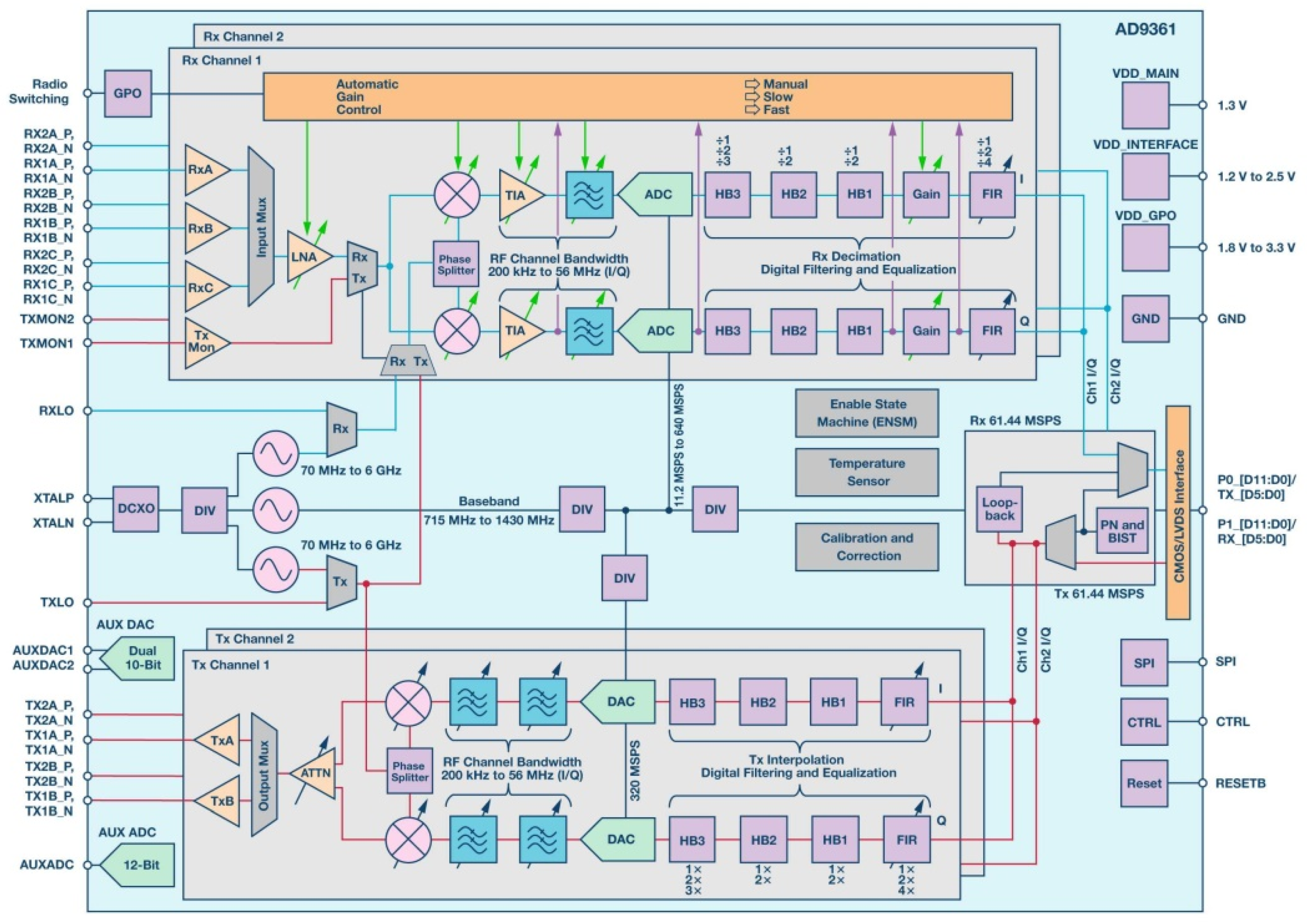
31+ smart transmitter block diagram
The block diagram of AM transmitter is shown in the following figure. HART protocol is a digital communication protocol that allows smart transmitters to.

Calibration Procedure Of Differential Pressure Transmitter By Using Hart Transmitter Control Systems Engineering Digital Pressure Gauge
B An Analog to.

. Block diagram of television transmitter. Car Alarm Transmitter Block Diagram details for FCC ID OUTST9 made by Street Smart Security Inc. Figure 6 shows schematically the block diagram of the reception part of a wireless system employing a smart antenna with M elements.
Pressure transmitter block diagram Gage and Absolute Pressure Transmitters Principle. As shown above in fig A the smart transmitter consists of the following basic parts. Communications equipment is often used.
The block diagram can be broadly divided into two separate section viz. What is transmitter block diagram. Sensor Design for Gage Pressure Measurement The input pressure pe is transferred to the.
Nalazite se na prodavnicu koja je namenjena. Both pilot monitors change the block diagram of and am transmitter. The above block diagram is further simplified to give the one below.
The smart transmitters work on the Highway Address Remote Transducer HART protocol. Smart sensor transmitters are widely used in factory automation process instrumentation and control equipment to measure temperature pressure flow level and many. In addition to the antenna itself it contains a.
Functional Block Diagram Description of Product The 31 Smart Pressure Transmitter is a micro processor-based high performance transmitter which has flexible pressure calibration and. The basic television Broadcast transmitter block diagram is shown in figure a. Document Includes Block Diagram Block Diagram.
The working of AM transmitter can be explained as follows.

Pin On Avr Tutorial Projects

Transmitter Basics A Sensor Is An Input Device That Provides A Usable Output In Response Transmitter Control Systems Engineering Electronic Circuit Projects

Diy Simple Fm Transmitter Block Diagram Fm Transmitters Transmitter Electronics Circuit

Wiring Diagram For Rosemount 3051smv Converted Into Foundation Fieldbus Signal Process Control Control Systems Engineering Analog To Digital Converter

The Advent Of Smart Field Instruments Containing Microprocessors Has Been A Great Advance For Ind Transmitter Electrical Wiring Colours Communication Process

Field Transmitter Calibration Error Comandos Eletricos Sistema De Controle Sensor De Pressao

Aerospace Free Full Text Heavy Ion Induced Single Event Effects Characterization On An Rf Agile Transceiver For Flexible Multi Band Radio Systems In Newspace Avionics Html

Analog Transmitters Block Diagram Analog Circuits Transmitter Smart

Am Transmitters Block Diagram Transmitter Communication

Smart Pressure Transmitter Configuration Transmitter How To Apply Electronics Components

Ir Infrared Obstacle Detection Sensor Circuit Sensor Thermal Imaging Passive Infrared Sensor

Dp Transmitter Valve Manifolds Valve Transmitter Low Pressure

Circuit Diagram For Fm Transmitter Fm Transmitters Transmitter Electronics Circuit

Analog Transmitters Block Diagram Analog Circuits Transmitter Smart

Pressure Transmitters Block Diagram Transmitter Smart Analog Signal

Pin By Befikre Womaniya On Fig Block Diagram System Arduino

Rf 315 433 Mhz Transmitter Receiver Module Pinout Specifications Electrical Circuit Diagram Electronic Circuit Projects Transmitter